
Honda Fit/Jazz - Fuel and Emissions System Description - L15A1(IN model) and L15A6
Fuel and Emissions System Description - L15A1(IN model) and L15A6
Electronic Control System
The functions of the fuel and emission control systems are managed by the engine control module (ECM) on vehicles with manual transmissions or the powertrain control module (PCM) on vehicles with automatic transmissions.
Fail-safe Function
When an abnormality occurs in a signal from a sensor, the ECM/PCM ignores that signal and assumes a pre-programmed value for that sensor that allows the engine to continue to run.Back-up Function
When an abnormality occurs in the ECM/PCM, the injectors are controlled by a back-up circuit independent of the system to permit minimal driving.Self-diagnosis
When an abnormality occurs in the signal from a sensor, the ECM/PCM supplies ground for the malfunction indicator lamp (MIL) and stores the diagnostic trouble code (DTC) in erasable memory. When the ignition is first turned on, the ECM/PCM supplies ground for the MIL for 2 seconds to check the MIL bulb condition.Two Driving Cycle Detection Method
To prevent false indications, the ‘‘two driving cycle detection method'' is used for some self-diagnostic functions. When an abnormality occurs, the ECM/PCM stores it in its memory. When the same abnormality recurs after the ignition switch is turned OFF and ON (II) again, the ECM/PCM informs the driver by turning on the MIL.ECM/PCM Data (L15A1 engine for IN model and L15A6 engine)
You can retrieve data from the ECM/PCM by connecting the HDS or the scan tool to the data link connector (DLC). The items listed in the table below conform to SAE recommended practice. The HDS also reads data beyond that recommended by SAE so that this data may help you find the causes of intermittent problems.
NOTE:
- The ‘‘operating values'' listed are approximate and may vary depending on the environment and the individual vehicle.
- Unless noted otherwise, ‘‘at idle speed'' means idling with the engine completely warmed up, CVT in Park or neutral, M/T in neutral position, and the A/C and all accessories turned off.
| Data | Description | Operating Value | Freeze Data |
|---|---|---|---|
| Diagnostic Trouble Code (DTC) | If the ECM/PCM detects a problem, it will store it as a code consisting of one letter and four numbers. Depending on the problem, an SAE-defined code (P0xxx) or a Honda-defined code (P1xxx) will be output to the tester. | If no problem is detected, there is no output. | YES |
| Engine Speed | The ECM/PCM computes engine speed from the signals sent from the crankshaft position (CKP) sensor. This data is used for determining the time and amount of injected fuel. | Nearly the same as tachometer indication At idle speed: L15A1 engine for IN model and L15A6 engine 750±50 rpm (min-1) | YES |
| Vehicle Speed | The ECM/PCM converts pulse signals from the vehicle speed sensor (VSS). | Nearly the same as speedometer indication | YES |
| Manifold Absolute Pressure (MAP) | The absolute pressure caused in the intake manifold by engine load and speed. | With engine stopped: Nearly the same as atmospheric pressure At idle speed: about 20-34 kPa (150-260 mmHg, 6-10 in.Hg), 0.7-1.1 V | YES |
| Engine Coolant Temperature (ECT) | The ECT sensor converts coolant temperature into voltage and signals the ECM/PCM. The sensor is a thermistor whose internal resistance changes with coolant temperature. The ECM/PCM uses the voltage signals from the ECT sensor to determine the amount of injected fuel. | With cold engine: Same as ambient temperature and IAT With engine warmed up: about 80-100 °C (176-212 °F), 0.5-0.8 V | YES |
| Primary Heated Oxygen Sensor (Primary HO2S), (Sensor 1) Secondary Heated Oxygen Sensor (Secondary HO2S) (Sensor 2) | The HO2S detects the oxygen content in the exhaust gas and sends voltage signals to the ECM/PCM. Based on these signals, the ECM/PCM controls the air fuel ratio. When the oxygen content is high (that is, when the ratio is leaner than the stoichiometric ratio), the voltage signal is lower. When the oxygen content is low (that is, when the radio is richer than the stoichiometric ratio), the voltage signal is higher. | 0.0-1.25 V At idle speed: about 0.1-0.9 V | NO |
ECM/PCM Data (L15A1 engine for IN model and L15A6 engine) (cont'd)
| Data | Description | Operating Value | Freeze Data |
|---|---|---|---|
| Fuel System Status | Fuel system status is indicated as ''open'' or ''closed''. Closed: Based on the A/F sensor and HO2S output, the ECM/PCM determines the air/fuel ratio and controls the amount of injected fuel. Open: ignoring the A/F sensor and HO2S output, the ECM/PCM refers to signals from the throttle position (TP), manifold absolute pressure (MAP), intake air temperature (IAT), barometric pressure (BARO) and engine coolant temperature (ECT) sensors to control the amount of injected fuel. | At idle speed: closed | YES |
| Short Term Fuel Trim | The air/fuel ratio correction coefficient for correcting the amount of injected fuel when the Fuel System Status is ‘‘closed''. When the ratio is leaner than the stoichiometric ratio, the ECM/PCM increases short term fuel trim gradually, and the amount of injected fuel increases. The air/fuel ratio gradually gets richer, causing a lower oxygen content in the exhaust gas. Consequently, the short term fuel trim is lowered, and the ECM/PCM reduces the amount of injected fuel. This cycle keeps the air/fuel ratio close to the stoichiometric ratio when in closed loop status. | 0.70-1.47 | YES |
| Long Term Fuel Trim | Long term fuel trim is computed from short term fuel trim and indicates changes occurring in the fuel supply system over a long period. If long term fuel trim is higher than 1.00, the amount of injected fuel must be increased. If it is lower than 1.00, the amount of injected fuel must be reduced. | 0.72-1.35 | YES |
| Intake Air Temperature (IAT) | The IAT sensor converts intake air temperature into voltage and signals the ECM/PCM. When intake air temperature is low, the internal resistance of the sensor increases, and the voltage signal is higher. | With cold engine: Same as ambient temperature and ECT | YES |
| Throttle Position | Based on the accelerator pedal position, the opening angle of the throttle valve is indicated. | At idle speed: about 10 %, 0.5 V | YES |
| Ignition Timing | Ignition timing is the ignition advance angle set by the ECM/PCM. The ECM/PCM matches ignition timing to the driving conditions. | At idle speed: 8 °±5 °BTDC when the SCS service signal line is jumped with the HDS | NO |
| Caluculated Load Valve (CLV) | CLV is the engine load calculated from the MAP data. | At idle speed: 12-34 % At 2,500 rpm (min-1) without load: 15-25 % | YES |
L15A1 engine for IN model and L15A6 engine
ECM/PCM Inputs and Outputs at Connector A (31P)
 NOTE: Standard battery voltage is 12 V.
| Terminal number | Wire color | Terminal name | Description | Signal |
|---|---|---|---|---|
| 1 | BLK/WHT | PHO2SHTC (PRIMARY HEATED OXYGEN SENSOR (PRIMARY HO2S) HEATER CONTROL) | Drives primary HO2S heater | With ignition switch ON (II): battery voltage With fully warmed up engine running: duty controlled |
| 2 | YEL/BLK | IGP2 (POWER SOURCE) | Power source for the ECM/PCM circuit | With ignition switch ON (II): battery voltage With ignition switch OFF: about 0 V |
| 3 | YEL/BLK | IGP1 (POWER SOURCE) | Power source for the ECM/PCM circuit | With ignition switch ON (II): battery voltage With ignition switch OFF: about 0 V |
| 4 | BLK | PG2 (POWER GROUND) | Ground for the ECM/PCM circuit | Less than 1.0 V at all times |
| 5 | BLK | PG1 (POWER GROUND) | Ground for the ECM/PCM circuit | Less than 1.0 V at all times |
| 6 | WHT | PHO2S (PRIMARY HEATED OXYGEN SENSOR (PRIMARY HO2S) SENSOR 1) | Detects primary HO2S sensor (sensor 1) signal | With throttle fully opened from idle with fully warmed up engine: about 0.6 V With throttle quickly closed: below 0.4 V |
| 7 | BLU | CKP (CRANKSHAFT POSITION SENSOR) | Detects CKP sensor signal | With engine running: pulses |
| 9 | RED/BLU | KS (KNOCK SENSOR) | Detects knock sensor signal | With engine knocking: pulses With ignition switch ON (II): about 0 V |
| 10 | GRN/BLK | SG2 (SENSOR GROUND) | Sensor ground | Less than 1.0 V at all times |
| 11 | GRN/WHT | SG1 (SENSOR GROUND) | Sensor ground | Less than 1.0 V at all times |
| 12 | BLK/BLU | IACV (IDLE AIR CONTROL (IAC) VALVE) | Drives IAC valve | With engine running: duty controlled |
| 13 | WHT/BLK | EGRP (EXHAUST GAS RECIRCULATION (EGR) VALVE POSITION SENSOR) | Detects EGR valve position sensor signal | With engine running: 1.2-2.0 V (depending on EGR valve lift) |
| 15 | RED/BLK | TPS (THROTTLE POSITION (TP) SENSOR) | Detects TP sensor signal | With throttle fully open: about 4.8 V With throttle fully closed: about 0.5 V |
ECM/PCM Inputs and Outputs at Connector A (31P)
NOTE: Standard battery voltage is 12 V.| Terminal number | Wire color | Terminal name | Description | Signal |
|---|---|---|---|---|
| 18*1 | BLU/WHT | VSS (VEHICLE SPEED SENSOR (VSS)) | Detects VSS signal | With ignition switch ON (II) and front wheels rotating: cycles 0-about 5 V or battery voltage |
| 18*2 | BLU/WHT | VABS (VEHICLE SPEED SIGNAL FROM ABS) | Input vehicle speed from ABS control unit | Depending on vehicle speed: pulses |
| 19 | RED/GRN | MAP (MANIFOLD ABSOLUTE PRESSURE (MAP) SENSOR) | Detects MAP sensor signal | With ignition switch ON (II): about 3 V At idle: about 1.0 V (depending on engine speed) |
| 20 | YEL/BLU | VCC2 (SENSOR VOLTAGE) | Provides sensor voltage | With ignition switch ON (II): about 5 V With ignition switch OFF: about 0 V |
| 21 | YEL/RED | VCC1 (SENSOR VOLTAGE) | Provides sensor voltage | With ignition switch ON (II): about 5 V With ignition switch OFF: about 0 V |
| 23 | BRN/YEL | LG2 (LOGIC GROUND) | Ground for the ECM/PCM circuit | Less than 1.0 V at all times |
| 24 | BRN/YEL | LG1 (LOGIC GROUND) | Ground for the ECM/PCM circuit | Less than 1.0 V at all times |
| 26 | GRN | CMP (CAMSHAFT POSITION (CMP) SENSOR) (TOP DEAD CENTER (TDC) SENSOR) | Detects CMP (TDC) sensor | With engine running: pulses |
| 27 | WHT/BLU | IGPLS4 (No. 4 IGNITION COIL PULSE) | Drives No. 4 ignition coil | With ignition switch ON (II): about 0 V With engine running: pulses |
| 28 | WHT/BLK | IGPLS3 (No. 3 IGNITION COIL PULSE) | Drives No. 3 ignition coil | |
| 29 | WHT/GRN | IGPLS2 (No. 2 IGNITION COIL PULSE) | Drives No. 2 ignition coil | |
| 30 | WHT | IGPLS1 (No. 1 IGNITION COIL PULSE) | Drives No. 1 ignition coil |
| *1: | M/T |
| *2: | CVT |
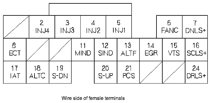
ECM/PCM Inputs and Outputs at Connector B (24P)
 NOTE: Standard battery voltage is 12 V.
| Terminal number | Wire color | Terminal name | Description | Signal |
|---|---|---|---|---|
| 2 | YEL | INJ4 (No. 4 INJECTOR) | Drives No. 4 injector | With ignition switch ON (II): battery voltage At idle: duty controlled |
| 3 | BLU | INJ3 (No. 3 INJECTOR) | Drives No. 3 injector | |
| 4 | RED | INJ2 (No. 2 INJECTOR) | Drives No. 2 injector | |
| 5 | BRN | INJ1 (No. 1 INJECTOR) | Drives No. 1 injector | |
| 6 | GRN | FANC (RADIATOR FAN CONTROL) | Drives radiator fan relay | With radiator fan running: about 0 V With radiator fan stopped: battery voltage |
| 7*2 | GRN/WHT | DNLS+ (CVT DRIVEN PULLEY CONTROL VALVE +SIDE) | Drives CVT driven pulley control valve | With ignition switch ON (II): pulsing signal |
| 8 | RED/WHT | ECT (ENGINE COOLANT TEMPERATURE SENSOR) | Detects ECT sensor signal | With ignition switch ON (II): about 0.1-4.8 V (depending on engine coolant temperature) |
| 11*3 | RED/WHT | MIND (M INDICATOR) | Drives M indicator light | With M indicator light turned ON: about 6 V With M indicator light turned OFF: 0 V voltage |
| 12*2 | LT GRN | SIND (S INDICATOR) | Drives S indicator light | With S indicator light turned ON: about 6 V With S indicator light turned OFF: 0 V voltage |
| 13 | WHT/RED | ALTF (ALTERNATOR FR SIGNAL) | Detects alternator FR signal | With engine running: about 0-5 V (depending on electrical load) |
| 14 | PNK | EGR (EXHAUST GAS RECIRCULATION (EGR) VALVE) | Drives EGR valve | With EGR operating: duty controlled With EGR not operating: about 0 V |
| 15 | GRN/YEL | VTS (VTEC SOLENOID VALVE) | Drivers VTEC solenoid valve | At idle: about 0V |
| 16*2 | YEL | SCLS+ (CVT START CLUTCH PRESSURE CONTROL VALVE +SIDE) | Drives CVT start clutch pressure control valve | With ignition switch ON (II): pulsing signal |
| 17 | RED/YEL | IAT (INTAKE AIR TEMPERATURE SENSOR) | Detects IAT sensor signal | With ignition switch ON (II): about 0.1-4.8 V (depending on intake air temperature) |
| 18 | WHT/GRN | ALTC (ALTERNATOR CONTROL) | Sends alternator control signal | With engine running: about 0-5 V (depending on electrical load) |
| 19*3 | LT GRN/RED | S-DN (DOWNSHIFT SWITCH) | Detects downshift switch signal | Steering shift switch pushed toward downshift position (marked with -): 0 V Steering shift switch in neutral position: about 5 V |
| 20*3 | YEL | S-UP (UPSHIFT SWITCH) | Detects upshift switch signal | Steering shift switch pushed toward upshift position (marked with +): 0 V Steering shift switch in neutral position: about 5 V |
| 21 | RED/YEL | PCS (EVAPORATIVE EMISSION (EVAP) CANISTER PURGE VALVE) | Drives EVAP canister purge valve | With engine running, engine coolant below 65 °C (149 °F): about 0 V With engine running, engine coolant above 65 °C (149 °F): duty controlled |
| 24*2 | BLU/WHT | DRLS+ (CVT DRIVE PULLEY CONTROL VALVE +SIDE) | Drives CVT drive pulley control valve | With ignition switch ON (II): duty controlled |
| *2: | CVT |
| *3: | HONDA CVT+7SPEED MODE system |
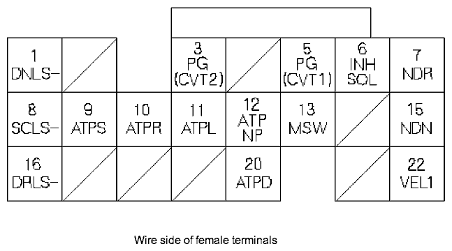
PCM Inputs and Outputs at Connector C (22P)*2
 NOTE: Standard battery voltage is 12 V.
| Terminal number | Wire color | Terminal name | Description | Signal |
|---|---|---|---|---|
| 1 | PNK/BLK | DNLS- (CVT DRIVEN PULLEY CONTROL VALVE -SIDE) | Drives CVT driven pulley control valve | |
| 3 | BLK | PG (CVT2) (POWER GROUND CVT2) | Ground for the PCM circuit | |
| 5 | BLK | PG (CVT1) (POWER GROUND CVT1) | Ground for the PCM circuit | |
| 6 | GRN/BLK | INHSOL (INHIBITOR SOLENOID CONTROL) | Drives inhibitor solenoid | With inhibitor solenoid ON: battery voltage With inhibitor solenoid OFF: 0 V |
| 7 | RED/BLU | NDR (CVT DRIVE PULLEY SPEED SENSOR) | Detects CVT drive pulley speed sensor signal | With ignition switch ON (II): 0 V or 5 V |
| 8 | PNK/BLU | SCLS- (CVT START CLUTCH PRESSURE CONTROL VALVE B -SIDE) | Drives CVT start clutch pressure control valve | |
| 9 | BLU/WHT | ATPS (TRANSMISSION RANGE SWITCH S POSITION) | Drives transmission range switch S position signal | In S position: 0 V In any other position: about 5 V or battery voltage |
| 10 | WHT | ATPR (TRANSMISSION RANGE SWITCH R POSITION) | Detects transmission range switch R position signal | In R position: 0 V In any other position: about 10 V |
| 11 | BLU | ATPL (TRANSMISSION RANGE SWITCH L POSITION) | Detects transmission range switch L position signal | In L position: 0 V In any other position: about 10 V |
| 12 | LT GRN | ATPNP (TRANSMISSION RANGE SWITCH NEUTRAL/PARK POSITION) | Detects transmission range switch Neutral/Park position signal | In Park or neutral: 0 V In any other position: about 10 V |
| 13*3 | YEL | MSW (MAIN SWITCH) | Detects main switch (7SPEED MODE) signal | Main switch (7SPPED MODE) pushed: 0 V Main switch (7SPPED MODE) released: about 5 V |
| 15 | WHT | NDN (CVT DRIVEN PULLEY SPEED SENSOR) | Detects CVT driven pulley speed sensor signal | With ignition switch ON (II): 0 V or 5 V |
| 16 | GRN/YEL | DRLS- (CVT DRIVE PULLEY CONTROL VALVE -SIDE) | Drives CVT drive pulley control valve | With ignition switch ON (II): pulses |
| 20 | PNK | ATPD (TRANSMISSION RANGE SWITCH D POSITION) | Detects transmission range switch D position signal | In D position: about 0 V In any other position: about 5 V |
| 22 | WHT/RED | VEL1 (CVT SPEED SENSOR) | Detects CVT speed sensor | Depending on vehicle speed: pulses When vehicle is stopped: about 0 V or about 5 V |
| *2: | CVT |
| *3: | HONDA CVT+7SPEED MODE system |
ECM/PCM Inputs and Outputs at Connector E (31P)
 NOTE: Standard battery voltage is 12 V.
| Terminal number | Wire color | Terminal name | Description | Signal |
|---|---|---|---|---|
| 2 | WHT/RED | SHO2S (SECONDARY HEATED OXYGEN SENSOR (SECONDARY HO2S), SENSOR 2) | Detects secondary HO2S (sensor 2) signal | With throttle fully opened from idle with fully warmed up engine: above 0.6 V With throttle quickly closed: below 0.4 V |
| 3 | BRN/YEL | LG3 (LOGIC GROUND) | Ground for the PCM control circuit | Less than 0.1 V at all times |
| 4 | PNK | SG3 (SENSOR GROUND) | Sensor ground | Less than 0.1 V at all times |
| 5 | GRN/WHT | FUP (FUEL INJECTION SIGNAL) | Sends fuel injection signal to gauge assembly | With ignition switch ON (II): pulses |
| 6 | BLK/WHT | SHO2SHTC (SECONDARY HEATED OXYGEN SENSOR (SECONDARY HO2S) HEATER CONTROL) | Drives secondary HO2S heater | With ignition switch ON (II): battery voltage With fully warmed up engine running: duty controlled |
| 7 | RED/YEL | MRLY (PGM-FI MAIN RELAY) | Drives PGM-FI main relay 1 Power source for the DTC memory | With ignition switch ON (II): about 0 V With ignition switch OFF: battery voltage |
| 8*3 | BLU/WHT | LED A | Drives shift indicator | In 7SPEED MODE:
|
| 9 | BLK/YEL | IG1 (IGNITION SIGNAL) | Detects ignition signal | With ignition switch ON (II): battery voltage With ignition switch OFF: about 0 V |
| 10 | GRN/YEL | FPR (FUEL PUMP RELAY) | Drives PGM-FI main relay 2 | 0 V for 2 seconds after turning ignition switch ON (II), then battery voltage |
| 11 | PNK | DIND (D INDICATOR) | Drives D indicator light | With D indicator light turned ON: about 6 V With D indicator light turned OFF: about 0 V |
| 12 | BLU | TAC | Detects evaporator sensor signal | With ignition switch ON (II): about 0.1-4.8 V (depending on evaporator temperature) |
| 13*2 | BLU/RED | SLC (SHIFT LOCK CONTROL) | Drives shift lock solenoid | With ignition switch ON (II), in Park position, brake pedal pressed, and accelerator pedal released: about 0 V |
| 15*4 | GRN/RED | ELD (ELECTRICAL LOAD DETECTOR (ELD)) | Detects ELD signal | With ignition switch ON (II): about 0.1-4.8 V (depending on electrical load) |
| *2: | CVT |
| *3: | HONDA CVT+7SPEED MODE system |
| *4: | L15A1 engine for IN model |
ECM/PCM Inputs and Outputs at Connector E (31P)
NOTE: Standard battery voltage is 12 V.| Terminal number | Wire color | Terminal name | Description | Signal |
|---|---|---|---|---|
| 18 | RED | ACC (A/C CLUTCH RELAY) | Drives A/C clutch relay | With compressor ON: about 0 V With compressor OFF: battery voltage |
| 20*3 | GRN/BLK | LED C | Drives shift indicator | In 7SPEED MODE:
|
| 21*3 | RED/WHT | LED B | Drives shift indicator | In 7SPEED MODE:
|
| 22 | WHT/BLK | BKSW (BRAKE PEDAL POSITION SWITCH) | Detects brake pedal position switch signal | With brake pedal released: about 0 V With brake pedal pressed: battery voltage |
| 23 | RED/WHT | K-LINE | Sends and receives scan tool signal | With ignition switch ON (II): battery voltage |
| 24 | GRN | MTRTW | Sends engine coolant temperature signal | With ignition switch ON (II): pulse |
| 25 | BLU/YEL | VSSOUT (VEHICLE SPEED SENSOR (VSS) OUTPUT SIGNAL) | Sends vehicle speed sensor signal | Depending on vehicle speed: pulses |
| 26 | BLU | NEP (ENGINE SPEED PULSE) | Outputs engine speed pulse | With engine running: pulses |
| 28 | BLU/WHT | ACS (A/C SWITCH SIGNAL) | Detects A/C switch signal | With A/C switch ON: 0 V With A/C switch OFF: about 5 V |
| 29 | BRN | SCS (SERVICE CHECK SIGNAL) | Detects service check signal | With the service check signal shorted with the PGM Tester: about 0 V With the service check signal opened: about 5 V |
| 30 | RED/BLU | WEN (WRITE ENABLE SIGNAL) | Detects write enable signal | With ignition switch ON (II): about 0V |
| 31 | GRN/ORN | MIL (MALFUNCTION INDICATOR LAMP) | Drives MIL | With MIL turned ON: about 0 V With MIL turned OFF: battery voltage |
| *3: | HONDA CVT+7SPEED MODE system |
Vacuum Hose Routing
Vacuum Distribution
L15A1 engine for IN model and L15A6 engine

PGM-FI System (L15A1 engine for IN model and L15A6 engine)
The programmed fuel injection (PGM-FI) system is a sequential multiport fuel injection system.
Air Conditioning (A/C) Compressor Clutch Relay
When the engine control module (ECM)/powertrain control module (PCM) receives a demand for cooling from the A/C system, it delays the compressor from being energized, and enriches the mixture to assure smooth transition to the A/C mode.Alternator Control
The alternator signals the ECM/PCM during charging.Barometric Pressure (BARO) Sensor
The BARO sensor is inside the ECM/PCM. It converts atmospheric pressure into a voltage signal that the ECM/ PCM use to modify the basic duration of the fuel injection discharge.Camshaft Position (CMP) Sensor
(Top Dead Center (TDC) Sensor)
The CMP (TDC) sensor detects the position of the No. 1 cylinder as a reference for sequential fuel injection to each cylinder.

Crankshaft Position (CKP) Sensor
The CKP sensor detects engine speed and determines ignition timing and timing for fuel injection of each cylinder.
Engine Coolant Temperature (ECT) Sensor
The ECT sensor is a temperature dependent resistor (thermistor). The resistor of the thermistor decreases as the engine coolant temperature increases.
Ignition Timing Control
The ECM/PCM contains the memory for basic ignition timing at various engine speeds and manifold absolute pressure. It also adjusts the timing according to engine coolant temperature.Injector Timing and Duration
The ECM/PCM contains the memory for basic discharge duration at various engine speeds and manifold pressures. The basic discharge duration, after being read out from the memory, is further modified by signals sent from various sensors to obtain the final discharge duration.By monitoring long term fuel trim, the ECM/PCM detects long term malfunctions in the fuel system, and will set a diagnostic trouble code (DTC).
Intake Air Temperature (IAT) Sensor
The IAT sensor is a temperature dependent resistor (thermistor). The resistance of the thermistor decreases as the intake air temperature increases.
Knock Sensor
The knock control system adjusts the ignition timing to minimize knock.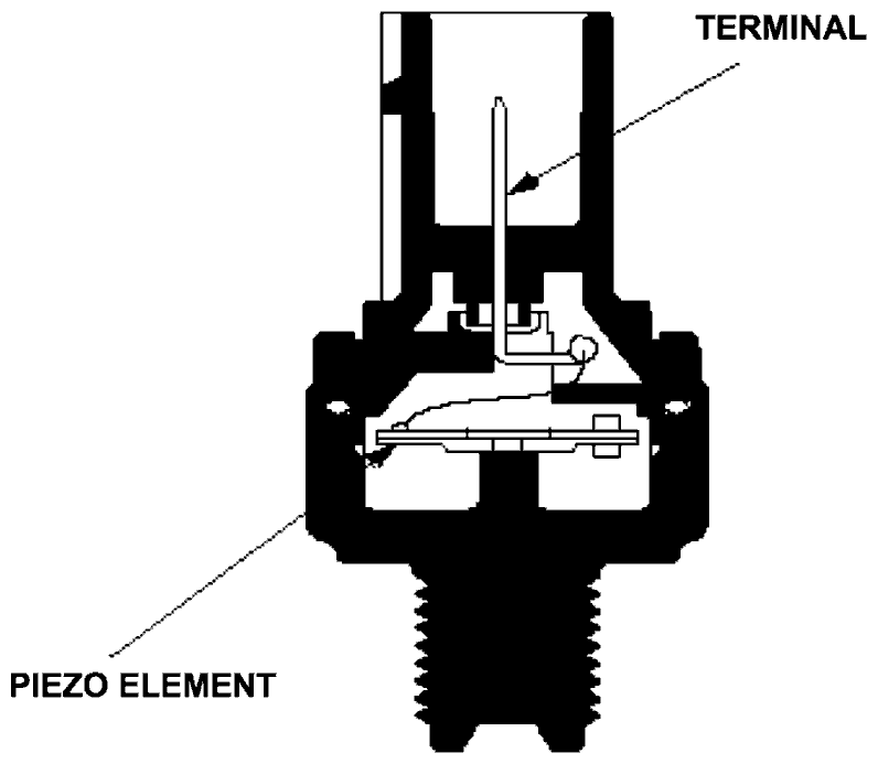
Manifold Absolute Pressure (MAP) Sensor
The MAP sensor converts manifold absolute pressure into electrical signals to the ECM/PCM.
Primary Heated Oxygen Sensor (Primary HO2S)
The primary HO2S detects the oxygen content in the exhaust gas and sends signals to the ECM/PCM which varies the duration of fuel injection accordingly. To stabilize its output, the sensor has an internal heater. The primary HO2S is installed in the exhaust manifold. By controlling the air fuel ratio with primary HO2S and secondary HO2S, the deterioration of the primary HO2S can be evaluated by its feedback period. When the feedback period exceeds a certain value during stable driving conditions, the sensor is considered deteriorated and the ECM/PCM sets a DTC.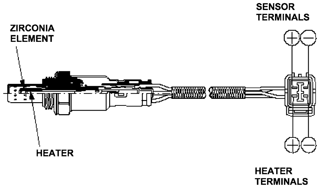
Secondary Heated Oxygen Sensor (Secondary HO2S)
The secondary HO2S detects the oxygen content in the exhaust gas downstream of the three way catalytic converter (TWC) and sends signals to the ECM/PCM which varies the duration of fuel injection accordingly. To stabilize its output, the sensor has an internal heater. The secondary HO2S is installed in the TWC.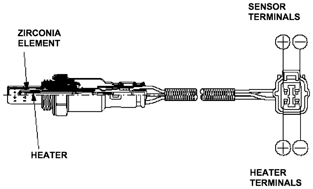
Starting Control
When the engine is started, the ECM/PCM provides a rich mixture by increasing injector duration.Throttle Position (TP) Sensor
The TP sensor is a potentiometer connected to the throttle valve shaft. As the throttle position changes, the sensor varies the signal voltage to the ECM/PCM. The TP sensor is not replaceable apart from the throttle body.
Vehicle Speed Sensor (VSS) (M/T model only)
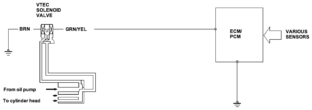
The VSS is driven by the differential. It generates a pulsed signal from an input of 5 volts. The number of pulses per minute increases/decreases with the speed of the vehicle.VTEC System (L15A1 engine for IN model and L15A6 engine)
- The VTEC system changes the cam profile to correspond to the engine speed by the VTEC solenoid valve.
It maximizes torque at low engine speeds and output at high engine speed. - The low lift cam is used at low engine speeds, and the high lift cam is used at high engine speeds.
Idle Control System
When the engine is cold, the A/C compressor is on, the transmission is in gear, the brake pedal is pressed, the power steering load is high, or the alternator is charging, the ECM/PCM controls current to the idle air control (IAC) valve to maintain the correct idle speed. Refer to the System Diagram to see the functional layout of the system.
Brake Pedal Position Switch
The brake pedal position switch signals the ECM/PCM when the brake pedal is pressed.Idle Air Control (IAC) Valve
To maintain the proper idle speed, the IAC valve changes the amount of air bypassing the throttle body in response to an electrical signal from the ECM/PCM.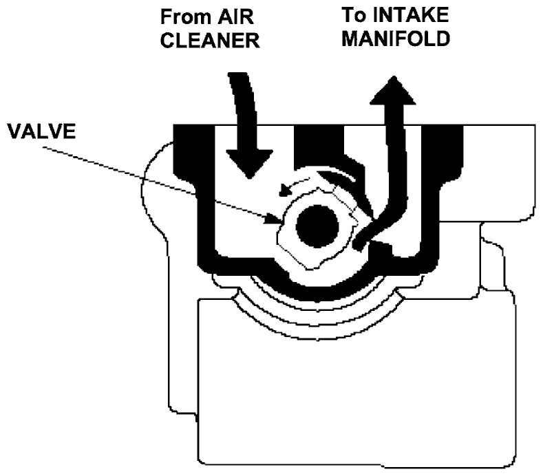
Fuel Supply System
Fuel Cut-off Control
During deceleration with the throttle valve closed, current to the injectors is cut off to improve fuel economy at speeds over 900 rpm (min-1). Fuel cut-off action also occurs when engine speed exceeds 6,200 rpm (min-1), regardless of the position of the throttle valve, to protect the engine from over-revving. When the vehicle is stopped, the PCM cuts the fuel at engine speeds over 6,200 rpm (min-1).Fuel Pump Control
When the ignition is turned on, the ECM/PCM grounds the PGM-FI main relay which feeds current to the fuel pump for 2 seconds to pressurize the fuel system. With the engine running, the ECM/PCM grounds the PGM-FI main relay and feeds current to the fuel pump. When the engine is not running and the ignition is on, the ECM/PCM cuts ground to the PGM-FI main relay which cuts current to the fuel pump.PGM-FI Main Relay 1 and 2
The PGM-FI relay consists of two separate relays. PGM-FI main relay 1 is energized whenever the ignition switch is ON (II) which supplies battery voltage to the ECM/PCM, power to the injectors, and power for PGM-FI main relay 2. PGM-FI main relay 2 is energized to supply power to the fuel pump for 2 seconds when the ignition switch is turned ON (II), and when the engine is running.Intake Air System
Refer to the System Diagram to see the functional layout of the system.
Throttle Body
The throttle body is a single-barrel side draft type. The lower portion of the IAC valve is heated by engine coolant from the cylinder head.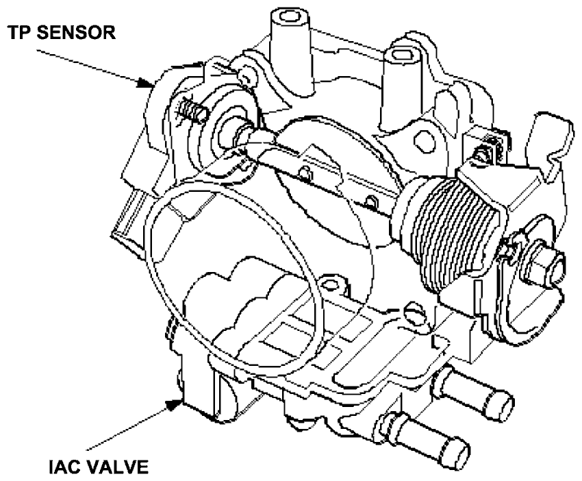
Catalytic Converter System
Three Way Catalytic Converter (TWC)
The TWC converts hydrocarbons (HC), carbon monoxide (CO), and oxides of nitrogen (NOx) in the exhaust gas to carbon dioxide (CO2), dinitrogen (N2), and water vapor.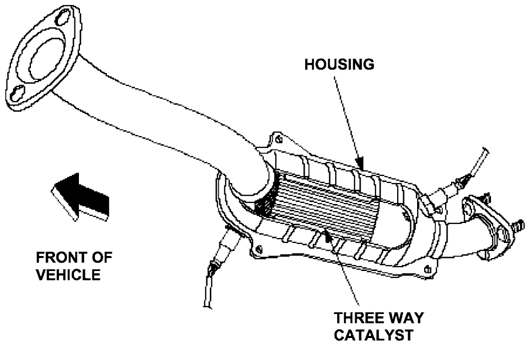
Positive Crankcase Ventilation (PCV) System (L15A1 engine for IN model and L15A6 engine)
The PCV valve prevents blow-by gasses from escaping into the atmosphere by venting them into the intake manifold.
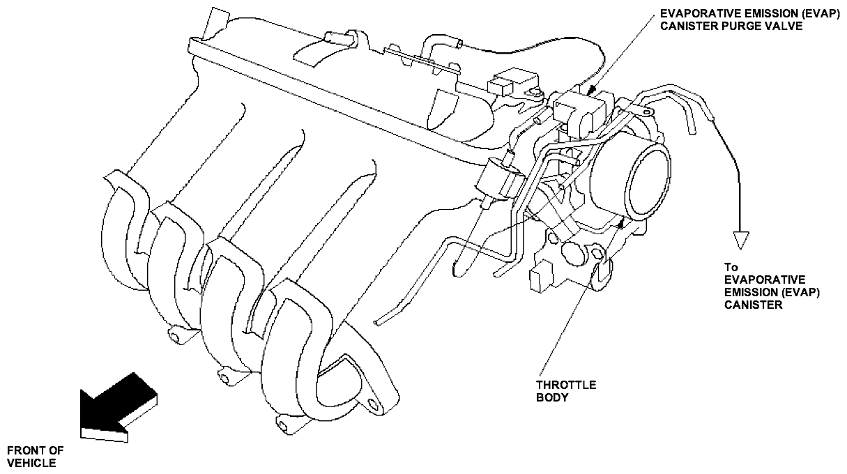
Evaporative Emission (EVAP) Control System
Refer to the System Diagram to see the functional layout of the system.
EVAP Canister
The EVAP canister temporarily stores fuel vapor from the fuel tank until it can be purged back into the engine and burned (refer to the System Diagram to see the functional layout of the system).EVAP Canister Purge Valve
When the engine coolant temperature is below 70 °C (158 °F), the ECM/PCM turns off the EVAP canister purge valve which cuts vacuum to the EVAP canister.Idle Control System Diagram (L15A1 engine for IN model and L15A6 engine)
The idle speed of the engine is controlled by the idle air control (IAC) valve:
- After the engine starts, the IAC valve opens for a certain amount of time. The amount of air is increased to raise the idle speed.
- When the engine coolant temperature is low, the IAC valve is opened to obtain the proper fast idle speed. The amount of bypassed air is thus controlled in relation to engine coolant temperature.

Intake Air System Diagram (L15A1 engine for IN model and L15A6 engine)
This system supplies air for engine needs. A resonator in the intake air pipe provides additional silencing as air is drawn into the system.
Exhaust Gas Recirculation (EGR) System Diagram (L15A1 engine for IN model and L15A6 engine)
The EGR system reduces oxides of nitrogen (NOx) emissions by recirculating exhaust gas through the EGR valve and the intake manifold into the combustion chambers. The ECM/PCM memory includes the ideal EGR valve position for varying operating conditions.
The EGR valve position sensor detects the amount of EGR valve lift and sends it to the ECM/PCM. The ECM/PCM then compares it with the ideal lift in its memory (based on signals sent from other sensors). If there is any difference between the two, the ECM/PCM cuts current to the EGR valve.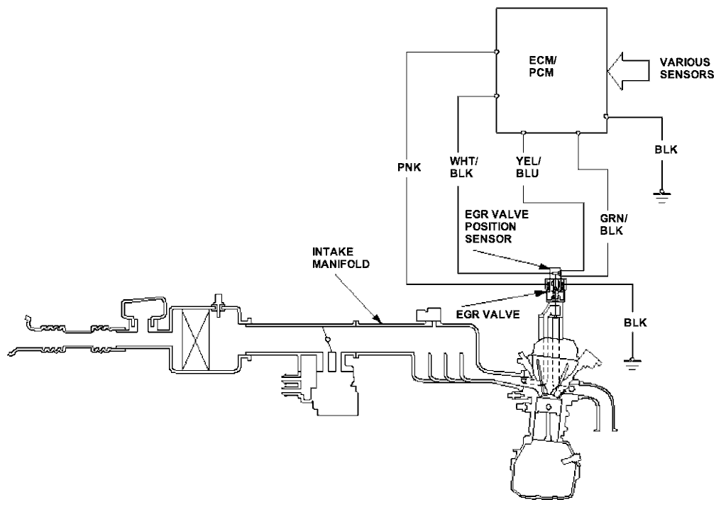
Evaporative Emission (EVAP) Control Diagram (L15A1 engine for IN model and L15A6 engine)
The EVAP controls minimize the amount of fuel vapor escaping to the atmosphere. Vapor from the fuel tank is temporally stored in the EVAP canister until it can be purged from the EVAP canister into the engine and burned.
- The EVAP canister is purged by drawing fresh air through it and into a port on the intake manifold.
The purging vacuum is controlled by the EVAP canister purge valve, which operates whenever engine coolant temperature is above 70 °C (158 °F). - When vapor pressure in the fuel tank is higher than the set value of the EVAP two way valve, the valve opens and regulates the flow of fuel vapor to the EVAP canister.
