Honda Fit/Jazz - Fuel and Emissions System Description - Supplement (L15A 5MT)

Fuel and Emissions System Description - Supplement
ECM/PCM Data
You can retrieve data from the ECM/PCM by connecting the scan tool or the Honda PGM Tester to the Data Link Connector (DLC). The items listed in the table below conform to SAE recommended practice. The Honda PGM Tester also reads data beyond that recommended by SAE so that this data may help you find the causes of intermittent problems.
NOTE:
- The ‘‘operating values'' listed are approximate and may vary depending on the environment and the individual vehicle.
- Unless noted otherwise, ‘‘at idle speed'' means idling with the engine completely warmed up, A/T in Park or neutral, M/T in neutral position, and the A/C and all accessories turned off.
| Data | Description | Operating Value | Freeze Data |
|---|---|---|---|
| Diagnostic Trouble Code (DTC) | If the ECM/PCM detects a problem, it will store it as a code consisting of one letter and four numbers. Depending on the problem, an SAE-defined code (P0xxx) or a Honda-defined code (P1xxx) will be output to the tester. | If no problem is detected, there is no output. | YES |
| Engine Speed | The ECM/PCM computes engine speed from the signals sent from the Crankshaft Position (CKP) sensor. This data is used for determining the time and amount of injected fuel. | Nearly the same as tachometer indication At idle speed: 750±50 rpm (min-1) | YES |
| Vehicle Speed | The ECM/PCM converts pulse signals from the Vehicle Speed Sensor (VSS). | Nearly the same as speedometer indication | YES |
| Manifold Absolute Pressure (MAP) | The absolute pressure caused in the intake manifold by engine load and speed. | With engine stopped: Nearly the same as atmospheric pressure At idle speed: about 20-34 kPa (150-260 mmHg, 6-10 in. Hg), 0.7-1.1 V | YES |
| Engine Coolant Temperature (ECT) | The ECT sensor converts coolant temperature into voltage and signals the ECM/PCM. The sensor is a thermistor whose internal resistance changes with coolant temperature. The ECM/PCM uses the voltage signals from the ECT sensor to determine the amount of injected fuel. | With cold engine: Same as ambient temperature and IAT With engine warmed up: about 80-100°C (176-212°F), 0.5-0.8 V | YES |
| Heated Oxygen Sensor (HO2S) | The HO2S detects the oxygen content in the exhaust gas and sends voltage signals to the ECM/PCM. Based on these signals, the ECM/PCM controls the air fuel ratio. When the oxygen content is high (that is, when the ratio is leaner than the stoichiometric ratio), the voltage signal is lower. When the oxygen content is low (that is, when the radio is richer than the stoichiometric ratio), the voltage signal is higher. | 0.0-1.25 V At idle speed: about 0.1-0.9 V | NO |
| Data | Description | Operating Value | Freeze Data |
|---|---|---|---|
| Fuel System Status | Fuel system status is indicated as ‘‘open'' or ‘‘closed''. Closed: Based on the HO2S output, the ECM/PCM determines the air/fuel ratio and controls the amount of injected fuel. Open: ignoring the HO2S output, the ECM/PCM refers to signals from the Throttle Position (TP), Manifold Absolute Pressure (MAP), Intake Air Temperature (IAT), Barometric Pressure (BARO) and Engine Coolant Temperature (ECT) sensors to control the amount of injected fuel. | At idle speed: closed | YES |
| Short Term Fuel Trim | The air/fuel ratio correction coefficient for correcting the amount of injected fuel when the Fuel System Status is ‘‘closed.'' When the ratio is leaner than the stoichiometric ratio, the ECM/PCM increases short term fuel trim gradually, and the amount of injected fuel increases. The air/fuel ratio gradually gets richer, causing a lower oxygen content in the exhaust gas. Consequently, the short term fuel trim is lowered, and the ECM/PCM reduces the amount of injected fuel. This cycle keeps the air/fuel ratio close to the stoichiometric ratio when in closed loop status. | 0.70-1.47 | YES |
| Long Term Fuel Trim | Long term fuel trim is computed from short term fuel trim and indicates changes occurring in the fuel supply system over a long period. If long term fuel trim is higher than 1.00, the amount of injected fuel must be increased. If it is lower than 1.00, the amount of injected fuel must be reduced. | 0.72-1.35 | YES |
| Intake Air Temperature (IAT) | The IAT sensor converts intake air temperature into voltage and signals the ECM/PCM. When intake air temperature is low, the internal resistance of the sensor increases, and the voltage signal is higher. | With cold engine: Same as ambient temperature and ECT | YES |
| Throttle Position | Based on the accelerator pedal position, the opening angle of the throttle valve is indicated. | At idle speed: about 10 %, 0.5 V | YES |
| Ignition Timing | Ignition timing is the ignition advance angle set by the ECM/PCM. The ECM/PCM matches ignition timing to the driving conditions. | At idle speed: 8° ± 5° BTDC when the SCS service signal line is jumped with the Honda PGM tester | NO |
| Caluculated Load Valve (CLV) | CLV is the engine load calculated from the MAP data. | At idle speed: 12-34 % At 2,500 rpm (min-1) with no load: 15-25 % | YES |
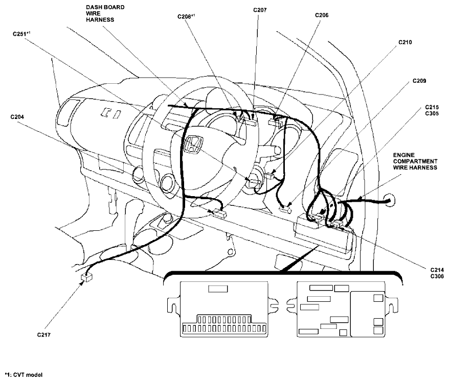
Vacuum Distribution

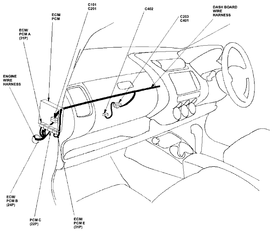
ECM/PCM Inputs and Outputs at Connector A (31P)
 NOTE: Standard battery voltage is 12 V.
| Terminal number | Wire color | Terminal name | Description | Signal |
|---|---|---|---|---|
| 1 | BLK/WHT | O2SHTC (HEATED OXYGEN SENSOR (HO2S) HEATER CONTROL) | Drives HO2S heater | With ignition switch ON (II): battery voltage With fully warmed up engine running: duty controlled |
| 2 | YEL/BLK | IGP2 (POWER SOURCE) | Power source for the ECM/PCM circuit | With the ignition switch ON (II): battery voltage With the ignition switch OFF: about 0 V |
| 3 | YEL/BLK | IGP1 (POWER SOURCE) | Power source for the ECM/PCM circuit | With the ignition switch ON (II): battery voltage With the ignition switch OFF: about 0 V |
| 4 | BLK | PG2 (POWER GROUND) | Ground for the ECM/PCM circuit | Less than 1.0 V at all times |
| 5 | BLK | PG1 (POWER GROUND) | Ground for the ECM/PCM circuit | Less than 1.0 V at all times |
| 6 | WHT | HO2S (HEATED OXYGEN SENSOR (HO2S) SENSOR 1) | Detects HO2S sensor signal | With throttle fully opened from idle with fully warmed up engine: about 0.6 V With throttle quickly closed: below 0.4 V |
| 7 | BLU | CKP (CRANKSHAFT POSITION SENSOR) | Detects CKP sensor signal | With engine running: pulses |
| 9 | RED/BLU | KS (KNOCK SENSOR) | Detects knock sensor signal | With engine knocking: pulses With ignition switch ON (II): about 0 V |
| 10 | GRN/BLK | SG2 (SENSOR GROUND) | Sensor ground | Less than 1.0 V at all times |
| 11 | GRN/WHT | SG1 (SENSOR GROUND) | Sensor ground | Less than 1.0 V at all times |
| 12 | BLK/BLU | IACV (IDLE AIR CONTROL (IAC) VALVE) | Drives IAC valve | With engine running: duty controlled |
| 13 | WHT/BLK | EGRP (EXHAUST GAS RECIRCULATION (EGR) VALVE POSITION SENSOR) | Detects EGR valve position sensor signal | With engine running: 1.2 V-2.0 V (depending on EGR valve lift) |
| 15 | RED/BLK | TPS (THROTTLE POSITION (TP) SENSOR) | Detects TP sensor signal | With throttle fully open: about 4.8 V With throttle fully closed: about 0.5 V |
ECM/PCM Inputs and Outputs at Connector A (31P)
NOTE: Standard battery voltage is 12 V.| Terminal number | Wire color | Terminal name | Description | Signal |
|---|---|---|---|---|
| 18*2 | BLU/WHT | VSS (VEHICLE SPEED SENSOR (VSS)) | Detects VSS signal | With ignition switch ON (II) and front wheels rotating: cycles 0 V-about 5 V or battery voltage |
| 18*1 | BLU/WHT | VABS (VEHICLE SPEED SIGNAL FROM ABS) | Input vehicle speed from ABS control unit | Depending on vehicle speed: pulses |
| 19 | RED/GRN | MAP (MANIFOLD ABSOLUTE PRESSURE (MAP) SENSOR) | Detects MAP sensor signal | With ignition switch ON (II): about 3 V At idle: about 1.0 V (depending on engine speed) |
| 20 | YEL/BLU | VCC2 (SENSOR VOLTAGE) | Provides sensor voltage | With ignition switch ON (II): about 5 V With ignition switch OFF: about 0 V |
| 21 | YEL/RED | VCC1 (SENSOR VOLTAGE) | Provides sensor voltage | With ignition switch ON (II): about 5 V With ignition switch OFF: about 0 V |
| 23 | BRN/BLK | LG2 (LOGIC GROUND) | Ground for the ECM/PCM circuit | Less than 1.0 V at all times |
| 24 | BRN/BLK | LG1 (LOGIC GROUND) | Ground for the ECM/PCM circuit | Less than 1.0 V at all times |
| 26 | GRN | TDC (TOP DEAD CENTER (TDC) SENSOR) | Detects DTC sensor | With engine running: pulses |
| 27 | WHT/BLU | IGPLS4 (No. 4 IGNITION COIL PULSE) | Drives No. 4 ignition coil | With ignition switch ON (II): about 0 V With engine running: pulses |
| 28 | WHT/BLK | IGPLS3 (No. 3 IGNITION COIL PULSE) | Drives No. 3 ignition coil | |
| 29 | WHT/GRN | IGPLS2 (No. 2 IGNITION COIL PULSE) | Drives No. 2 ignition coil | |
| 30 | WHT | IGPLS1 (No. 1 IGNITION COIL PULSE) | Drives No. 1 ignition coil |
*2: M/T
ECM/PCM Inputs and Outputs at Connector B (24P)
 NOTE: Standard battery voltage is 12 V.
| Terminal number | Wire color | Terminal name | Description | Signal |
|---|---|---|---|---|
| 2 | YEL | INJ4 (No. 4 INJECTOR) | Drives No. 4 injector | With ignition switch ON (II): battery voltage At idle: duty controlled |
| 3 | BLU | INJ3 (No. 3 INJECTOR) | Drives No. 3 injector | |
| 4 | RED | INJ2 (No. 2 INJECTOR) | Drives No. 2 injector | |
| 5 | BRN | INJ1 (No. 1 INJECTOR) | Drives No. 1 injector | |
| 6 | GRN | FANC (RADIATOR FAN CONTROL) | Drives radiator fan relay | With radiator fan running: about 0 V With radiator fan stopped: battery voltage |
| 7*1 | GRN/WHT | DNLS+ (CVT DRIVEN PULLEY CONTROL VALUE+ SIDE) | Drives CVT driven pulley control value | With ignition switch ON (II): pulsing signal |
| 8 | RED/WHT | ECT (ENGINE COOLANT TEMPERATURE SENSOR) | Detects ECT sensor signal | With the ignition switch ON (II): about 0.1-4.8 V (depending on engine coolant temperature) |
| 11*1 | RED/WHT | M IND (M INDICATOR) | Drives M indicator light. | With M indicator light turned ON : about 6 V With M indicator light turned OFF : 0 V voltage |
| 12*1 | LT GRN | S IND (S INDICATOR) | Drives S indicator light. | With S indicator light turned ON : about 6 V With S indicator light turned OFF : 0 V voltage |
| 13 | WHT/RED | ALTF (ALTERNATOR FR SIGNAL) | Detects alternator FR signal | With engine running:about 0 V-5 V (depending on electrical load) |
| 14 | PNK | EGR (EXHAUST GAS RECIRCULATION (EGR) VALVE) | Drives EGR valve | With EGR operating: duty controlled With EGR not operating: about 0 V |
| 15 | GRN/YEL | VTS (VTEC SOLENOID VALVE) | Drivers VTEC solenoid valve | At idle: about 0V |
| 16*1 | YEL | SCLS+ (CVT START CLUTCH PRESSURE CONTROL VALVE + SIDE | Drives CVT start clutch pressure control valve | With ignition switch ON (II): pulsing signal |
| 17 | RED/YEL | IAT (INTAKE AIR TEMPERATURE SENSOR) | Detects IAT sensor signal | With ignition switch ON (II): about 0.1 V-4.8 V (depending on intake air temperature) |
| 18 | WHT/GRN | ALTC (ALTERNATOR CONTROL) | Sends alternator control signal | With engine running: about 0 V-5 V (depending on electrical load) |
| 19*1 | LT GRN/RED | S-DN (DOWN SHIFT SWITCH) | Detects downshift switch signal | Steering shift switch pushed toward downshift position (marked with -): 0 V Steering shift switch in neutral position : about 5 V |
| 20*1 | YEL | S-UP (UP SHIFT SWITCH) | Detects upshift switch signal | Steering shift switch pushed toward upshift position (marked with +): 0 V Steering shift switch in neutral position : about 5 V |
| 21 | RED/YEL | PCS (EVAPORATIVE EMISSION (EVAP) CANISTER PURGE VALVE) | Drives EVAP canister purge valve | With engine running, engine coolant below 65°C (149°F): about 0 V With engine running, engine coolant above 65°C (149°F): duty controlled |
| 24*1 | BLU/WHT | DRLS+ (CVT DRIVE PULLEY CONTROL VALVE + SIDE) | Drives CVT drive pulley control valve | With ignition switch ON (II): duty controlled |
| *1: CVT |
PCM Inputs and Outputs at Connector C (22P)*1
 NOTE: Standard battery voltage is 12 V.
| Terminal number | Wire color | Terminal name | Description | Signal |
|---|---|---|---|---|
| 1 | PNK/BLK | DNLS- (CVT DRIVEN PULLEY CONTROL VALVE - SIDE | Drives CVT driven pulley control valve | |
| 3 | BLK | PG (CVT2) (POWER GROUND CVT2) | Ground for the PCM circuit | |
| 5 | BLK | PG (CVT1) (POWER GROUND CVT1) | Ground for the PCM circuit | |
| 6 | GRN/BLK | INHSOL (INHIBITOR SOLENOID CONTROL) | Drives inhibitor solenoid | With inhibitor solenoid ON: battery voltage With inhibitor solenoid OFF: 0 V |
| 7 | RED/BLU | NDR (CVT DRIVE PULLEY SPEED SENSOR) | Detects CVT drive pulley speed sensor signal | With ignition switch ON (II): 0 V or 5 V |
| 8 | PNK/BLU | SCLS- (CVT START CLUTCH PRESSURE CONTROL VALVE B-SIDE) | Drives CVT start clutch pressure control valve | |
| 9 | BLU/WHT | ATPS (TRANSMISSION RANGE SWITCH S POSITION) | Drives transmission range switch S position signal | In S position: 0 V In any other position: about 5 V or battery voltage |
| 10 | WHT | ATPR (TRANSMISSION RANGE SWITCH R POSITION) | Detects transmission range switch R position signal | In R position: 0 V In any other position: about 10 V |
| 11 | BLU | ATPL (TRANSMISSION RANGE SWITCH L POSITION) | Detects transmission range switch L position signal | In L position: 0 V In any other position: about 10 V |
| 12 | LT GRN | ATPNP (TRANSMISSION RANGE SWITCH NEUTRAL/PARK POSITION) | Detects transmission range switch Neutral/Park position signal | In Park or Neutral: 0 V In any other position: about 10 V |
| 13 | YEL | MSW (MAIN SWITCH) | Detects main switch (7SPEED MODE) signal | Main switch (7SPPED MODE) pushed: 0 V Main switch (7SPPED MODE) released: about 5 V |
| 15 | WHT | NDN (CVT DRIVEN PULLEY SPEED SENSOR) | Detects CVT driven pulley speed sensor signal | With ignition switch ON (II): 0 V or 5 V |
| 16 | GRN/YEL | DRLS- (CVT DRIVE PULLEY CONTROL VALVE-SIDE) | Drives CVT drive pulley control valve | With ignition switch ON (II): pulses |
| 20 | PNK | ATPD (TRANSMISSION RANGE SWITCH D POSITION) | Detects transmission range switch D position signal | In D position: about 0 V In any other position: about 5 V |
| 22 | WHT/RED | VEL1 (CVT SPEED SENSOR) | Detects CVT speed sensor | Depending on vehicle speed: pulses When vehicle is stopped: about 0 V or about 5 V |
| *1: CVT |
ECM/PCM Inputs and Outputs at Connector E (31P)
 NOTE: Standard battery voltage is 12 V.
| Terminal number | Wire color | Terminal name | Description | Signal |
|---|---|---|---|---|
| 1 | GRN/YEL | IMO FPR (IMMOBILIZER FUEL PUMP RELAY) | Drives PGM-FI main relay 2 | 0 V for 2 seconds after turning ignition switch ON (II), then battery voltage |
| 3 | BRN/YEL | LG3 (LOGIC GROUND) | Ground for the PCM control circuit | Less than 0.1 V at all times |
| 4 | PNK | SG3 (SENSOR GROUND) | Sensor ground | Less than 0.1 V at all times |
| 5 | GRN/WHT | FUP (FUEL INJECTION SIGNAL) | Sends fuel injection signal to gauge assembly | With ignition switch ON (II): pulses |
| 7 | RED/YEL | MRLY(PGM-FI MAIN RELAY) | Drives PGM-FI main relay 1 Power source for the DTC memory | With ignition switch ON (II): about 0 V With ignition switch OFF: battery voltage |
| 8*1 | BLU/WHT | LED A | Drives shift indicator | In 7SPEED MODE:
|
| 9 | BLK/YEL | IG1 (IGNITION SIGNAL) | Detects ignition signal | With ignition switch ON (II): battery voltage With ignition switch OFF: about 0 V |
| 11 | PNK | DIND (D INDICATOR) | Drives D indicator light | With D indicator light turned ON: about 6 V With D indicator light turned OFF: 0 V |
| 12 | BLU | TAC | Detects evaporator sensor signal | With ignition switch ON (II): about 0.1-4.8 V (depending on evaporator temperature) |
| 13*1 | BLU/RED | SLC (SHIFT LOCK CONTROL) | Drives shift lock solenoid | With ignition switch ON (II) ,in Park position,brake pedal pressed,and accelerator pedal released: 0V |
| 15 | GRN/RED | ELD (ELECTRICAL LOAD DETECTOR (ELD)) | Detects ELD signal | With ignition switch ON (II): about 0.1-4.8 V (depending on electrical load) |
| *1: CVT |
ECM/PCM Inputs and Outputs at Connector E (31P)
NOTE: Standard battery voltage is 12 V.| Terminal number | Wire color | Terminal name | Description | Signal |
|---|---|---|---|---|
| 18 | RED | ACC (A/C CLUTCH RELAY) | Drives A/C clutch relay | With compressor ON: about 0 V With compressor OFF: battery voltage |
| 20*1 | GRN/BLK | LED C | Drives shift indicator | In 7SPEED MODE:
|
| 21*1 | RED/WHT | LED B | Drives shift indicator | In 7SPEED MODE:
|
| 22 | WHT/BLK | BKSW (BRAKE PEDAL POSITION SWITCH) | Detects brake pedal position switch signal | With brake pedal released: about 0 V With brake pedal pressed: battery voltage |
| 23 | RED/WHT | K-LINE | Sends and receives scan tool signal | With ignition switch ON (II): battery voltage |
| 24 | GRN | MTRTW | Sends engine coolant temperture signal | With ignition switch ON (II): pulse |
| 25 | BLU/YEL | VSSOUT (VEHICLE SPEED SENSOR (VSS) OUTPUT SIGNAL) | Sends vehicle speed sensor signal | Depending on vehicle speed: pulses |
| 26 | BLU | NEP (ENGINE SPEED PULSE) | Outputs engine speed pulse | With engine running: pulses |
| 27 | RED/BLU | IMOCD (IMMOBILIZER CODE) | Detects immobilizer signal | |
| 28 | BLU/WHT | ACS (A/C SWITCH SIGNAL) | Detects A/C switch signal | With A/C switch ON: 0 V With A/C switch OFF: about 5 V |
| 29 | BRN | SCS (SERVICE CHECK SIGNAL) | Detects service check signal | With the service check signal shorted with the PGM Tester: about 0 V With the service check signal opened: about 5 V |
| 30 | RED/BLU | WEN (WRITE ENABLE SIGNAL) | Detects write enable signal | With ignition switch ON (II): about 0V |
| 31 | GRN/ORN | MIL (MALFUNCTION INDICATOR LAMP) | Drives MIL | With MIL turned ON: about 0 V With MIL turned OFF: battery voltage |
| *1: CVT |
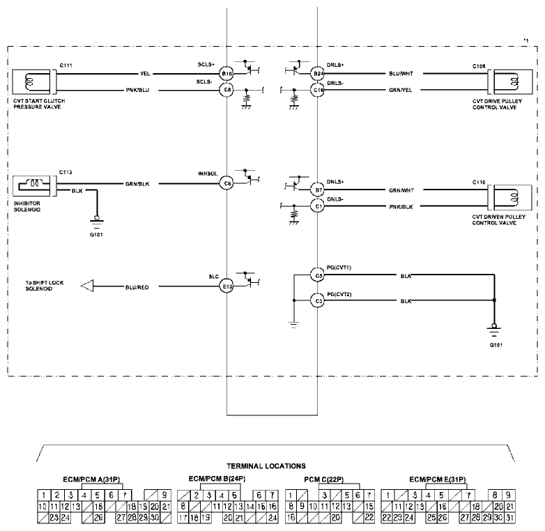
ECM/PCM Circuit Diagram

ECM/PCM Circuit Diagram (cont'd)


ECM/PCM Circuit Diagram (cont'd)


ECM/PCM Circuit Diagram (cont'd)
ECM/PCM Circuit Diagram (cont'd)
ECM/PCM Circuit Diagram (cont'd)


ECM/PCM Circuit Diagram (cont'd)


ECM/PCM Circuit Diagram (cont'd)

ECM/PCM Circuit Diagram (cont'd)

ECM/PCM Circuit Diagram (cont'd)