Advertisement [ ? ]
Site Links
- Lease Calculator
- Advertise on 10,100+ pages
- My Car ongoing Review
- Members' Chat
- Cars For Sale
- Car Dealers
- Honda "Fit" Manual
- Hyperflex Bushings
- For Sale
- Fix your Car
- Car Manuals
- other manuals - Reference Materials
- DIY Repairs
- Articles
- Video
- Link with Us
- Search Help
- Code your Mac!
- Fly, race, anything R/C
- DIY repair guides
- Z-Seven
- Mechanic's Blog
- Free Files
Vane Airflow VAF Sensors

Airflow sensors are used on engines with multiport electronic fuel injection. This is because the amount of fuel delivered by an EFI system is controlled by a computer (powertrain control module or PCM) which turns the fuel injectors on and off. The airflow sensor keeps the computer informed about how much air is being pulled into the engine past the throttle plates. This input along with information from other engine sensors allows the computer to calculate how much fuel is needed. The computer then increases or decreases injector duration (on time) to provide the correct air/fuel ratio.
On engines equipped with Throttle Body Injection (TBI) or a Speed-Density type of EFI system (most Chryslers and some GM applications), air flow is not measured directly but is estimated using inputs from the throttle position, manifold air temperature and manifold absolute pressure (MAP) sensors. But on engines with airflow EFI systems, airflow is measured directly by a vane airflow (VAF) sensor, a mass airflow sensor, or on some Japanese applications, a "Karman-Vortex" airflow sensor.
VANE AIRFLOW APPLICATIONS
Vane airflow sensors (also called airflow meters) are found mostly on German imports equipped with Bosch L-Jetronic fuel injection, Japanese imports equipped with Nippondenso multiport electronic fuel injection (made under Bosch license), and Ford vehicles equipped with the Bosch multiport EFI (such as Escort/Lynx, Turbo T-Bird and Mustang with the 2.3L turbo engine, Ford Probe with the 2.2L engine), and various other makes and models of vehicles.
HOW A VANE AIRFLOW SENSOR WORKS
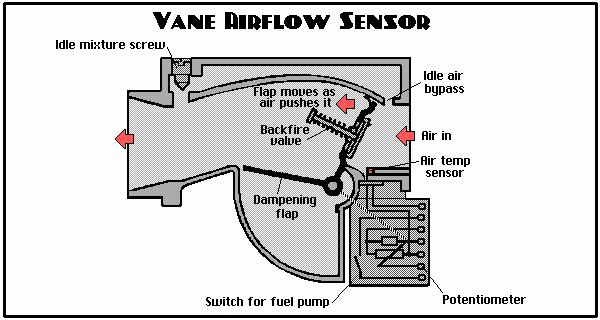
A vane airflow sensor is located ahead of the throttle and monitors the volume of air entering the engine by means of a spring-loaded mechanical flap. The flap is pushed open by an amount that is proportional to the volume of air entering the engine. The flap has a wiper arm that rotates against a sealed potentiometer (variable resistor or rheostat), allowing the sensor's resistance and output voltage to change according to airflow. The greater the airflow, the further the flap is forced open. This lowers the potentiometer's resistance and increases the voltage return signal to the computer.
The vane airflow sensor also contains a safety switch for the electric fuel pump relay. Airflow into the engine activates the pump. So if the engine won't start because the fuel pump won't kick in, the problem may be in the airflow sensor. The easiest to check the safety switch is to turn the ignition key on and push the flap open. If the fuel pump does not come on, the contact inside the sensor is probably defective.
A sealed idle mixture screw is also located on the airflow sensor. This controls the amount of air that bypasses the flap, and consequently the richness or leanness of the fuel mixture.
VANE AIRFLOW SENSOR PROBLEMS
Vane airflow sensors as well as all the other types of airflow sensors can't tolerate air leaks. Air leaks downstream of the sensor can allow "unmetered" or "false" air to enter the engine. The extra air can lean out the fuel mixture causing a variety of driveability problems, including lean misfire, hesitation and stumbling when accelerating, and a rough idle.
Dirt can also cause problems. Unfiltered air passing through a torn or poor fitting air filter can allow dirt to build up on the flap shaft of a vane airflow sensor causing the flap to bind or stick. The operation of the flap can be tested by gently pushing it open with a finger. It should open and close smoothly with even resistance. If it binds or sticks, a shot of carburetor cleaner may loosen it up otherwise the sensor will have to be replaced.
Backfiring in the intake manifold can force the flap backwards violently, often bending or breaking the flap. Some sensors have a "backfire" valve built into the flap to protect the flap in case of a backfire by venting the explosion. But the antibackfire valve itself can become a source of trouble if it leaks. A leaky backfire valve will cause the sensor to read low and the engine to run rich.
VANE AIRFLOW SENSOR DIAGNOSIS
For Bosch applications, there is a special Bosch tester to check the output of the sensor. But a technician can also check a vane airflow sensor by using a multimeter to check the voltage and resistance values between the sensor's various terminals.
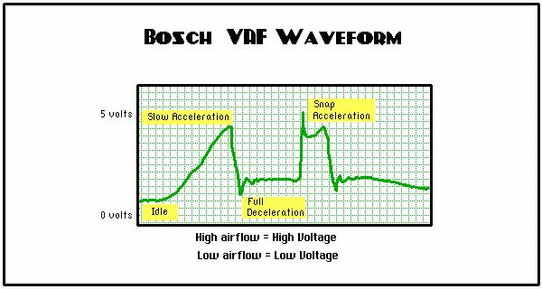
As a rule, the sensor's output voltage should rise from around 0.25 volts up to about 4.5 volts as the flap goes from closed to open. If the voltage reading is low, the reference voltage from the computer (VRef) should also be checked (it should be 5 volts on most applications).

Watching a vane airflow sensor's output on a digital storage oscilloscope (DSO) is a good way to detect "skips" or dead spots in the sensor's internal potentiometer. A good sensor should produce a smooth and gradual voltage transition from idle to wide open throttle. Changes in the sensor's voltage output should also produce a corresponding change in fuel injector duration when the engine is running. Injector duration should increase as the VAF flap is pushed open.
The rheostat that senses the position of the air flap most often becomes worn in the positioin just above idle to about 20% throttle. This is where most problems are likely to occur.
Vane airflow sensors are not serviceable, so must be replaced if there are any internal problems with the unit. We12ve heard of people taking the sensor housing apart and using electronics cleaner to clean the rheostat contacts. This may restore normal operation if the contacts are not worn, but it would be no help if the sensor has an electronic fault or a damaged flap.
Back to Driveability Diagnostics Emissions | Back to Info Main Page
Total messages: 0
